

 |
 |
Wiring
|
Serial Adaptor
|
|
|
SLT / DIN / STD |
 |
||||||||||||||||||||||||||||||||||||||||||||||||||||||||||||
|
DB9 Wiring Table
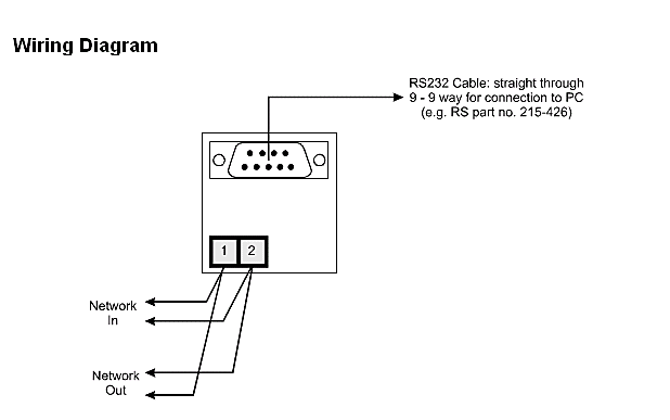
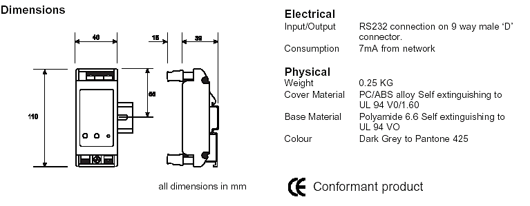
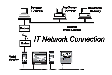
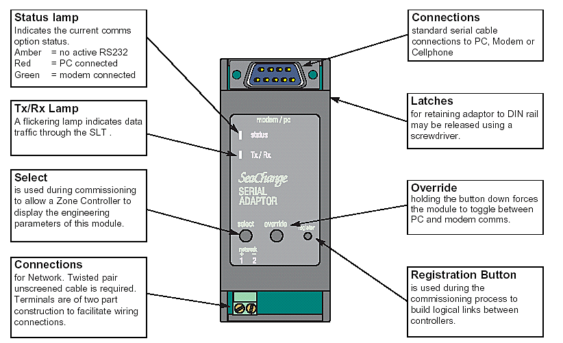
Please note, pins 4 and 8 are internally connected within the SLT.The SLT uses RS232 signal levels as its serial interface. This is widely used in PC's as the comm port interface. If your modern PC does not have an RS232 comm port, use a USB to serial adaptor to provide this functionality. This can be purchased through smartKontrols as part number CAB/USB/DB9.The SLT can swap the directions of TxD and RxD automatically so as to be able to connect to a PC and to a modem without the use of a special cable. The cable used is either a Female DB9 to Female DB9 for a direct PC connection, or Female DB9 to Male DB9/DB25 for a Modem connection.For non-specific interfaces the minimum signal requirement for the SLT to operate are RxD, TxD, GND, and either DSR or CTS (as input to SLT). It is prudent to connect all of these signals plus DTR and RTS if available, as the devie attached to the SLT may need these to operate correctly.Hardware flow control (handshake) signals DTR, DSR, RTS, and CTS are used by the SLT to detect the presence of a device. These are not used for hardware flow control. When no device is connected to the SLT, the status LED turns amber.Specification |
||||||||||||||||||||||||||||||||||||||||||||||||||||||||||||
 |
||||||||||||||||||||||||||||||||||||||||||||||||||||||||||||
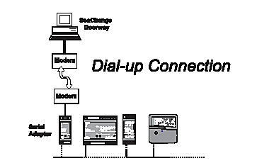
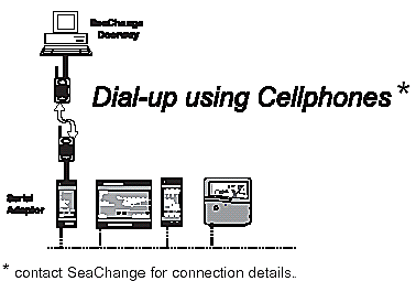
Typical Examples |
||||||||||||||||||||||||||||||||||||||||||||||||||||||||||||
 |
||||||||||||||||||||||||||||||||||||||||||||||||||||||||||||
 |
||||||||||||||||||||||||||||||||||||||||||||||||||||||||||||
 |
||||||||||||||||||||||||||||||||||||||||||||||||||||||||||||
 |
||||||||||||||||||||||||||||||||||||||||||||||||||||||||||||
Typical Features |
||||||||||||||||||||||||||||||||||||||||||||||||||||||||||||
 |
ENER-G House
Daniel Adamson Road
Salford
Manchester
M5 2DT
phone 0161 7457450
fax 0161 7457457
www.energ.com
www.seachange.co.uk
www.smartkontrols.co.uk