| Feature Notes |
Configuration Tables | Data Sheet Not yet Released |
Wiring | History |
Feature Notes |
Datasheet |
|
|
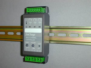
Multi Channel Controller |
Latest released version is 4d1 (beta)Document last updated 02/01/2002 |
MCC / DIN / 3T / ... |
Main FeaturesFor use primarily with Underfloor Heating ManifoldsProvides individual control of up to 3 individual zone valves/pumpsEach zone channel can be associated to its own independent
Zone Controller |
 |
SPTY = 0 |
A constant temperature set to the value of maximum Flow MAXF |
SPTY = 1 |
A setpoint which varies linearly between a maximum and a minimum value based on the zone trim signal. |
SPTY = 2 |
A setpoint which varies linearly between a maximum and a minimum value based on the average zone trim signal. |
Target Module |
OCDS setting |
HSC |
Heat Source number |
CSC |
Cool Source number +25 |
AHU |
AHU number +50 |
DHW |
Zone number( maximum 100) +100 |
Heating Option |
Cooling Option |
Output A |
Output B |
Output C |
/ 101 |
/ 201 |
Zone A Enable |
Zone B Enable |
Zone C Enable |
Input Configuration |
|
Input 3-4 |
Temp Sensor (optional); |
Input 5-6 ‘temp’ |
Temp Sensor (optional) |