Feature Notes
|
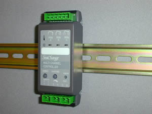
Multi Channel Controller
with 3 x Triac Outputs
|
|
MCC / DIN / 3T
|
Main Features
For use primarily with Underfloor Heating Manifolds
Provides individual control of up to 3 individual zone valves/pumps
Each zone channel can be associated to its own independent Zone Controller
|
 |
Description of Features
The Multi Channel Controller is a derivative of the Secondary
Circuit Controllers.
Initially only available in Heating version (with Cooling
versions to follow) for control of Underfloor heating solenoids. Two or three
outputs can be driven independantly from Zone demands. Demand collation still
available and demands can be passed on to other secondary controllers. Weather
compensation and local temperature control is not available.
Functional description
This controller provides control of solenoids or pumps on
an underfloor heating manifold. Each output is wired to a separate solenoid
thus three circuits can be controlled by one controller. The room temperature
control is provided by a Zone Controller for each room and the three Zone Controllers
are registered to the Secondary Controller.
Linking Zones to Output channels
Knobs K3, K4 and K5 are used to set the zone number
appropriate for each output channel, so if Knob 3 ZONA is set to 5 then
the heating demand from Zone 5 is used to control the driver on channel A. The
default driver setting is for Time proportioning driver with a minimum on time
of 10 seconds.
Note the outputs will not become active unless the Controller
is Occupied, this is determined by the highest Demand being greater than minimum
demand MIND. External overides and OCDS could also be used to
determine Occupancy as in a standard Secondary Circuit Controller.
If Knob 5 ZONC is set to zero then the third channel
can be used for a Fan or Pump as in the standard product.
The sense of the Outputs can be reversed by setting configuration variable
IVOP, this is useful if the solenoid valves being used are reverse acting.
Note this feature ONLY operates if the driver type is set to 2 (Sequence and
time proportioning)
CT setpoint
The configuration parameter SPTY setpoint type is retained
to allow the CT setpoint to be calculated in the same way as for standard secondary
controllers, the highest demand will be converted to a setpoint which will be
passed on to the Boiler controller. Note the weather compensation setting is
not available.
The secondary circuit can be controlled (by setting SPTY)
as:-
SPTY = 0 |
A constant temperature set to the value of maximum Flow MAXF
|
SPTY = 1 |
A setpoint which varies linearly between a maximum and a minimum value
based on the zone trim signal. |
SPTY = 2 |
A setpoint which varies linearly between a maximum and a minimum value
based on the average zone trim signal. |
The controller receives zone trim demands from zone controllers
which are utilising it's heat output and these demands are used to modify the
setpoint for the secondary circuit. The controller passes on it's demand to
the Boiler Controller in the form of a CT setpoint. (This action may be modified
by the setting of HTCT). This setpoint is 10 degrees above the setpoint
for the secondary circuit but this offset may be varied with the LOSS
config variable.
When there is insufficient demand from the zone controllers
the controller operates with a frost or non occupied setpoint (10C). See later
section Occupation State.
Demand Signaling
An extra configuration parameter has been introduced
which selects whether the demand signaling is via % demand or Constant temperature
setpoints. This is in line with similar changes made in Zone and DHW controllers.
Since the CT temperature range already has setup parameters the parameter in
the Secondary controller is only 0 or 1. HTCT (CTCT in cooling
version) set to 1 will force the controller to send the demand as a CT setpoint.
The Secondary Controllers will now decode received Constant
Temperature demands by converting them into a percentage demand and then prioritising
this demand along with any other demands which are being received. This has
been included so that the Controller still operates even if the sending controller
has incorrectly been setup to send a Constant Temperature setpoint. This practice
should be avoided wherever possible because the rescaling takes extra processing
time and will limit the demand fan in which the controller can handle. HTCT
setting in any controller should only be set if the target Controller is a Boiler
and the Heat is being taken off the Primary of the Boiler.
Occupation State
The occupied or non-occupied state of the controller is determined
by the settings of minimum demand MIND.
MIND minimum demand
The highest trim signal from the zones is compared with
this value and if greater the Controller is put into occupied mode. Once occupied
the trim signal from the zone must drop below half the MIND setting to
select non-occupied
Frost Protection
When the controller is non-occupied then the Frost
protection controls become active.
Frost Alarm from the Boiler
If this alarm is received and the FRPT parameter
is set then the controller will open all active outputs to allow the water to
circulate arround the underfloor circuits.
Frost Setpoint breached
The controller has a default frost setpoint of 10degC,
if a temperature sensor(s) is fitted and it reads a lower temperature than the
Frost setpoint and CMDE is non zero then the control outputs will become
active and a demand signal will be sent to the Boiler. A maximum of two sensor
are available so two of the circuits can be explicitely protected, if both are
connected set SACT to lowest. In practice a single circuit can probably
be taken as representative of all the circuits as far as frost protection is
concerned.
Occupation Destination
The controller can send it's Occupancy state to any
other module which supports receiving OCDS, at present that is AHU, DHW,
and other HSC or CSC controllers. This enables the demand fan-in, with filtering
if appropriate to be done on a secondary controller which then sets say a Fresh
Air AHU to run. To avoid the inevitable confusion regarding whether a demand
link or an OCDS link is being made this feature is restricted to manual
setting of OCDS in the sending controller, the table sets out the rules
for OCDS numbering. Secondary Controllers will OR the Occupancy signal
which arrives via OCDS with the normal Occupancy calculation. If the
OCDS signal is the only occupancy signal then the controller creates
a 'simulated demand' of 100%
Target Module |
OCDS setting |
HSC |
Heat Source number |
CSC |
Cool Source number +25 |
AHU |
AHU number +50 |
DHW |
Zone number( maximum 100) +100 |
External Source for Occupation State
The controller retains the standard features but only overrides
to OFF have any operational significance. For example a window contact or pump
alarm could be used to force non-occupancy which would shut all the valves.
The Secondary controller now supports input mode which allows
an external input to be used to provide an occupancy signal or an Alarm. The
VFC is wired into 'temp a' (centre pair of terminals) and the configuration
parameter INMD is set to between 1 and 5, see configuration table.
Input Mode set to 5 enables a Pump Fail Alarm
When input mode INMD 1 (AND function) is used the
external input can be used to 'enable' normal control, when the input is shorted
the controller responds to the heat demands received from other controllers,
when the input is open circuit the controller shuts down. This could be linked
to a flow fail signal or other similar interlock.
If the external source is to be the only occupation signal
then ensure that no other devices are pointing to the Secondary Controller's
Heat or Cool source.
Pump Alarm
If a single pump is being controlled by the Controller
then the state of this pump can be monitored with a readback signal, by wiring
a Flow switch or contactor auxilliary contact to 'input a'. Set input mode INMD
to 5 to select the Pump Alarm. An alarm will be generated if the readback is
not true within 30 seconds of the pump being started. The sense of the readback
signal can be changed with Alarm State ALST, if ALST is 0 then
a short circuit should be applied when the pump is running. Remember that Alarm
Mode ALRM set to zero disables all alarms.
If switch Interlock Pump ILKP is set then if a pump
fail is detected the control outputs will be shut down and will remain in this
state until the next change of occupancy or until the override button is pressed.
The error led will flash red to indicate that a shut down has occured.
Status Monitoring
The two inputs on the controller can be utilised for
Status monitoring if they are not being used for Temperature Control or Occupancy
control (see above). The State of the input can be read on Configuration parameter
C180 for input a and C181 for input b. If using input b for monitoring make
sure that the control loops are disabled by setting Control Mode CMDE
to zero.
Registration
The Controller must be registered with a Boiler Controller,
the first controller so registered is designated Heat Source 2 , (the boiler
itself being heat source 1).
Zone Controllers (or AHUs and FCUs) are registered to the
Secondary Circuit Controller(VT) by putting the Secondary Controller into Config
mode and pressing the registration button on all zones which use heat (or cool
for CSC versions) from this circuit. The VT controller will change the HTSC
variable in the zone controllers to match it's heat source number. Note leave
at least 10 seconds between the registration of each zone.
If the heat source number for the circuit is known and the
zone controller has already been registered with the boiler, the same effect
can be achieved by simply changing the HTSC config variable on the Zone
controller to the appropriate heat source number.
Registration of the cooling CSC version is the same except
the CLSC parameter is updated, the first controller registered is designated
number 2.
Configuration changes this issue
Many changes have been made to the configuration parameters
to allow for the multi Channel controller compared with the standard Secondary
CIrcuit Controller. New knobs allow for allocating Zone Numbers to the channels,
new sensors show the demands on each channel, and the weather compensation parameters
have been removed.
IVOP InVert OutPut inverts the operation of the output
triacs on all channels using driver type 2. This allows for reverse acting valves
to be accomodated.
Alarm Mode ALRM has an extra state which alows the
controller to be shut down only on STOP alarms.
Frost Protect FRPT has an additional state to allow
for pump only frost operation.
Options and Product Codes
Multi Channel Controller
MCC / DIN / 3T / [driver option]
Driver options
Heating Option |
Cooling Option |
Output A |
Output B |
Output C |
/ 101 |
/ 201 |
Zone A Enable |
Zone B Enable |
Zone C Enable |
| |
Input Configuration |
Input 3-4 |
Temp Sensor (optional);
or VFC status / alarm / occupancy (optional) |
Input 5-6 ‘temp’ |
Temp Sensor (optional) |
ENER-G Controls
ENER-G House
Daniel Adamson Road
Salford
Manchester
M5 2DT
phone 0161 7457450
fax 0161 7457457
www.energ.com
www.seachange.co.uk
www.smartkontrols.co.uk