Feature
|
Configuration Tables |
Data Sheet |
Wiring |
History |
Feature Notes |
Datasheet |
|
|
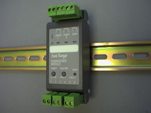
Changeover Submodule |
Latest released version is 4c2Document last updated 26/03/2003 |
PCO / DIN / 3T / ... |
Main FeaturesControls a Pair of Pumps or Fans providing Auto Changeover and Duty RotationCan use Contactor status signals or Flow Proving Switches (single or dual)Hours Run logged for each PumpPump Fail alarm output |
 |
Input 3-4 |
Pump 1 flow status |
Input 5-6 |
Pump 2 flow status |
NOAL |
No Alarms. |
FLFA |
Flow Failed pump A output 1 |
FLFB |
Flow Failed pump B output 2 |
DPMF |
Dual Pump Failure. |
STOP |
System STOP alarm received. |
FMD = 1 |
Standby pump output remains on. |
FMD = 2 |
Standby pump output remains on. |
FMD = 3 |
Standby pump output turned off. |
ACLR = 1 |
Pumps reset automatically after Occupancy; if |
ACLR = 0 |
Pumps remain latched in Failure Mode until |
ACLR = 1 |
Changeover Submodule sends special STOP alarm on
DPMF condition. |
ACLR = 1 |
DHW outputs are not held off while alarms |
ACLR = 0 |
DHW outputs are not held off while alarms |
ACLR = 1 |
In Secondary Circuit Controller: ILKP = 1 |
Option |
Output A |
Output B |
Output Spare |
Registered to BLR |
Registered to ZON/ZSL/DHW |
/ 001 |
Pump A |
Pump B |
Alarm Sounder |
Primary Pumps |
|
/ 002 |
Pump A |
Pump B |
Alarm Sounder |
VT Pumps |
|
/ 003 |
Pump A |
Pump B |
Alarm Sounder |
DHW Pumps |
|
/ 004 |
Pump A |
Pump B |
Alarm Sounder |
Heating Optimum Start Switch |
|
/ 005 |
Pump A |
Pump B |
Alarm Sounder |
Heating Occupation Switch |
|
/ 006 |
Pump A |
Pump B |
Alarm Sounder |
Heating Demand |
|
/ 007 |
Pump A |
Pump B |
Alarm Sounder |
Cooling Optimum Start Switch |
|
/ 008 |
Pump A |
Pump B |
Alarm Sounder |
Cooling Occupation Switch |
|
/ 009 |
Pump A |
Pump B |
Alarm Sounder |
Cooling Demand |
Input Configuration |
|
Input 3-4 ‘status 1’ |
VFC status pump A |
Input 5-6 ‘status 2’ |
VFC status pump B |