Feature
Notes

Configuration Tables

Data Sheet

Wiring

History

Feature Notes

Datasheet


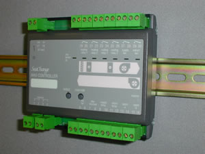
Air Handing Unit Controller
SUP version for Variable Supply Temperature Control (SPTY 2&5)

Latest released version is 4c2

Document last updated 03/11/2003
Recent features not included on Data sheet are in
RED text

AHU / DIN / SUP / [battery types] / [housekeeping] / [variant]

Main Features

Controls Supply & Extract Fans, Heating and Cooling Batteries

More complex Air Handling Units controlled by adding modules

AHU may feed single or multiple zones

Variable Supply Air Temperature, based on demand from Zones

Demand signals fed to Main Plant automatically

Summary Features

User Features

Occupation Times for the spaces served by the AHU are set on Zone Controllers. The AHU will run if any of the Zones are in their Occupation or Warm-Up period, thus providing Optimum Start of the AHU.
Alternatively the AHU can be set so that it will only run if the space is demanding heating or cooling.

Engineering Features

Automatic “Plug-and-Play” engineering using SeaChange Pushbutton Registration.
Demand Signals for Heating and Cooling are automatically fed back to main plant so that Boilers and Chillers only run when needed.
Control of more complex AHUs (e.g. with Preheater, Heat recovery, Multiple Heating or Cooling Stages, Humidity Control etc.) is achieved by adding further modules.
Interlocks are used by additional modules automatically.
Configuration Parameters may be set using a Zone Controller or SeaChange Doorway.

General Control Description

The AHU Controller will control supply (off-coil) temperature to a variable setpoint, which it will determine from Heating and Cooling demand signals received either from Zone / Terminal Unit Controllers, or from another AHU Controller which is acting as a “master”. The Controller will accept multiple demand signals, which may be all Cooling demands, all Heating demands, or a mixture of Cooling and Heating, and will calculate setpoint accordingly.
Maximum and Minimum values can be set for Heating and Cooling setpoints. A return air temperature sensor may be fitted, either for monitoring purposes, or because it is needed for Night Cooling (see later) or by another module (eg Mixing Damper Controller or Heat Recovery Controller).
Heating and cooling batteries may be “wet” ie. coils fed with LPHW and Chilled water, controlled by raise/lower type valves, or they may be staged electric batteries, switched by external contactors.
Supply and Extract Fans are interlocked with the batteries to ensure correct operation. It is possible to select whether the supply or extract starts first, to ensure positive or negative pressurisation of the building.

Description of Features

Temperature Control

The AHU Controller will control supply (off-coil) temperature to a variable setpoint which will be automatically adjusted according to demand signals for Heating and Cooling received from other controllers (either Zone or Terminal Unit Controllers in the controlled space, or another AHU Controller of the Return Air Control type which is feeding the same space and acting as a “master”).Parameters MAXS and MINS are used to set Maximum and Minimum setpoints for Supply Air Temperature (see diagram). Parameter SPDB creates a deadband which will prevent cycling between heating and cooling and reduce energy usage.
The AHU Controller will receive demand signals from many other controllers simultaneously. The Controller will calculate a Mid-Setpoint based on these demand signals. If all of the Zone demands are for heating, the Maximum will be taken, and used to set the Mid-Setpoint between MAXS and the midpoint between MAXS and MINS. If the Zone demands are all cooling demands, the Mid-Setpoint will be chosen to be between MINS and the midpoint. If there are a mixture of heating and cooling demands, the average of the 2 maxima are used to select the Mid-Setpoint.
The Deadband SPDB is now used to generate the working Heating and Cooling setpoints; only one of these will be active (unless HCOK is set, see below), and may be displayed on Monitoring parameter SPSL.
Heating and cooling batteries may be “wet” i.e. coils fed with LPHW and Chilled water, controlled by raise/lower type valves, or they may be staged electric batteries, switched by external contactors. The correct product variant should be selected to suit the combination of wet or electric batteries (see below).
Normally, the AHU will run for the whole of the Occupancy period of the registered Zones; if desired, it can be made to switch off if no demand for heating or cooling exists. Setting MIND to a non-zero value will cause the AHU to switch off if all Zone demands drop below the MIND setting.

SPTY 2 : Supply Temperature scheduled to Heat and Cool demands from multiple Zones

Designed to be used when a central Tempered Air plant supplies fresh air to a multi-zone building.
The registration procedure is to put AHU into config then register all subservient zones , ZON LCD, ZSL LCD, ZSL RLY, are currently supported, the ZSL version of the Fan Coil will also be able to be registered in this way. ZON LCD's will report HSCS 51,CLSC 51 for AHU 1 etc. as the zone is registered. Pre issue 3a zones only support Heat/Cool sources up to 20 so cannot be used.

The setpoint for the Supply Air control is calculated from the MAXS, MINS config limits using the heating and cooling demands. The combined demand (heating-cooling) is used to calculate the supply setpoint in the range -100% to +100% for MINS to MAXS. In this way the tempered air supply can be made to assist the warm up or cool down of the building.
When using a Zone controller to perform the Space temperature control (AHU SPTY=2) it is useful to be able to use the Zone controller temperature at the AHU as the return air temperature, this then allows correct control of Mixing Dampers. When registering a Zone in this mode the Zone temperature will be networked to the AHU. A hard wired a return air sensor will take precidence over the networked value.
As part of the registration process the Zone is setup to send it's Measured temperature, the value being used for control which might be an average, max or min of two sensors, to the AHU as if it were a networked sensor. The AHU uses this temperature as a measure of Return Air temperature, this is critical if mixing dampers or heat recovery modules are being utilised. If the AHU also has Slave AHU's which it is supply setpoint supervising, this return air temperature is also passed on to the Slave AHU's.
If it is practical to make a return air measurement then this should be done because this measurement will take into account heat gains through light fittings etc. A wired in sensor will take precidence over the networked value received from the zone.

AHU Master Slave Control

This allows one 'master AHU' to provide the Return Air control for a large space and to send its Supply Setpoint to one or more 'Slave AHU's'

The Master must be operating in mode SPTY 0 - 4, i.e. must be measuring and controlling Supply temperature. Also to prevent too much confusion in sorting out the logical links the Master may NOT also be a System Master for registration purposes.

The 'Slave' must be operating in mode SPTY 5. The registration process involves putting the master into config mode and then pressing the registration button on all the 'Slave AHU's'. The Slave will be registered again flashing it's status led green as normal, then after 5 seconds the error led will flash green to indicate the master ahu number.

The Slaves are put into the same group as the Master AHU, any number of Slaves can be linked to a single Master. If the master is receiving Return temperature from a networked sensor (or Zone Controller) then the return temperature will also be available at all the slaves.

If a Slave AHU is subsequently linked to a Zone Controller the link to the Master AHU will automatically be broken.

SPTY 5 :(SLAVE MODE) Supply Temperature control, Occupancy and Supply setpoint from Master AHU Controller

In this mode the Supply Air setpoint being used in the Master AHU is sent to the Slave. This setpoint can be 'modified' with the SPTR setpoint trim config variable to compensate for local conditions.
The master AHU can now be operating in any mode 0 through 4 and have slave AHU's registered to it.

Simultaneous Heating and Cooling

Normally, simultaneous use of the heating and cooling batteries is automatically prevented. However, under certain circumstances it may be necessary: either when Dehumidifying the Supply Air (see Humidity Control) or because staged cooling is being used.
With staged (DX) cooling, large step changes to the supply air temperature may be experienced when the stage is switched on and off. If this is not permissible, and a modulating heater battery is provided, this can be enabled at the same time as the staged cooling battery. Although this is not energy efficient, it may be the only way to achieve stable control of temperature using the mechanical plant provided.
To enable simultaneous heating and cooling, set parameter HCOK to 1. (Note: do not adjust this parameter when using dehumidifying control).

Occupancy Control

If using one of the Control modes based on Occupancy, it is possible to prevent the AHU from starting for Optimum Start or Fabric Protection, this would be appropriate for Fresh Air plants which only need to run when the building is occupied. A config variable OCCO (Occupation only) when set to 1 provides this feature. Otherwise the AHU will start for all Occupancy states other than non Occupied. The associated Zone Controller must be version ZON3b or later.

Occupation Destination

The config variable OCDS has been added which allows the Occupancy state of one AHU to be passed to another AHU or indeed to any SeaChange module wich supports receipt of the Occupancy status (DHW for example). This might be used when a number of tempered Air plants needs to run if any zone in the building is occupied. The Occupaction status of the Zones can be collated by one AHU as normal then it's occupancy state can be passed to the next and so on. Simply set the OCDS parameter to point to the required device (AHU number plus 50) and ensure that the receiving AHU is operating in SPTY 0, 3 or 6.

Humidity Control

If the AHU Controller is equipped with a Cooling battery and is appropriately constructed (with condensate trays, baffles etc.), it is possible to De-Humidify the Supply Air by applying full cooling. If the dew point of the incoming air is higher than the off-coil temperature, condensation will occur, thus de-humidifying the air. The Heater Battery can now be used to reheat the air to the required temperature; this will mean allowing Heating and Cooling Batteries to run simultaneously (which is normally prohibited). Setting a non-zero value for RHSP (see below) automatically allows simultaneous heating and cooling.
Parameters RHSP and RHDB set the Return (or Space) Humidity setpoint and deadband respectively; setting RHSP to a non-zero value enables Dehumidification control. If the Return Air Humidity rises above: (setpoint + 1/2 of the deadband) the supply air cooling setpoint will be depressed to drive the cooling coil fully open. It will stay in this mode until the Return Air Humidity falls to: (setpoint - 1/2 of the deadband) when normal temperature control will resume.
The Supply heating loop remains active and this will endeavour to maintain the required supply temperature. Note when operating in De-Hum mode the HCOK must be set to zero, the heating and cooling operation is handled by the De-Hum control logic.
A Networked Temp + Rh sensor must be fitted in the Return Air (or in the space) and registered as a Submodule to the AHU Controller (see Registration, later). Supply and Outside T+Rh sensors can also be registered to the AHU Controller for monitoring purposes.
Humidification of the Supply Air using a Humidifier may be controlled by a Humidity Controller Submodule. Also, a different regime of Hum / DeHum control can be used to give tighter control of Rh; see Humidity Controller Data Sheet for further details.
If  Close Humidity control is being used then the AHU De-Hum features are not used and RHSP must be set to zero to disable them. In this case the Hum and De-Hum are controlled by the Humidity controller and the Cooling coil override will take place automatically when the Humidity controller is setup.

Dessicant AHU control modules

The AHU can be used as the base controller for controlling Dessicant Cooled AHU's, The following special control modules can be registered to the AHU to create a Dessicant AHU solution. The special control modules take in the Heat demand% and Cool Demand% from the AHU, and rescale it to produce either a direct output to the driver stages or a setpoint to an interposing control loop.
Please contact smartkontrols for further information on the control modules below, or follow the links in History/Issue Notes.
Thermal Wheel/Evaporative Cooler controller registered as Mixing Damper/Heat Recovery [A1M1]
Dessicant Wheel/ReGen heater controller registered as Actuator, register first [A1C1]
Motor Speed controller, fan speed as function of Outside temperature, registered as Actuator [A1C2]
Supply Air Evaporative Cooler, Humidity controller with CMDE=0, registers as HUM [A1H1]

Mixing Damper control

A Damper controller can be setup to use the mixing dampers as the first stage of heating and cooling control. This allows modulation of the dampers without the need for a mixed air temperature sensor. The AHU needs to have a Return Air temperature values, either hard wired or networked and an Outside temperature value in order to determine the sense of operation of the dampers (heating or cooling).
If the damper is used as part of the heating/cooling sequence a configuration parameter in the Damper controller DMPC is set to the percentage of heat and cool demand which will be utilised by the damper controller. In this case the AHU driver re-scaling needs to be set up so that the AHU heating and cooling outputs do not start until the damper sequence is completed. So if DMPC (DeMand PerCent) in the Damper controller is set to 25%, then the minimum driver rescale parameters for heat and cool (HRMN,CRMN) should also be set to 25%.

Fan Control

Supply and Extract fans may be switched (via a contactor) directly from the outputs on the controller. Alternatively, the fan outputs may be used to open isolation dampers (if fitted) and limit switches on the dampers used to start the fan; this ensures that fresh air and exhaust dampers are fully open before the fans start, so as to avoid damage to the damper blades.
The parameter SFRT may be used to determine which fan starts first; some buildings (e.g.. clean rooms) need to be positively pressurised, in which case the supply fan should start first. Other buildings (e.g.. hospitals) require the opposite; the parameter should be set accordingly.
Fans will normally run if any of the registered zones are in Occupancy, Optimum Start or Fabric Protect mode. If desired, the AHU can be made to shut down if no heating or cooling demand exists, by setting MIND to a non-zero value.
The fan is also subject to an automatic start delay, which is determined according to the address of the controller. This ensures that, where a building has multiple AHUs, all of the fans do not start at once, thus causing a high peak electrical load. AHUs will start with 10 second intervals between them.
This provides a 10 second delay between AHU units on the same subnet. The maximum delay is 100 seconds.
Fans are subject to a Minimum-Run time (parameter MRUN) which ensures fans do not cycle on and off too frequently.

Frost Protection

If the Heating and Cooling Batteries are “wet”, the Controller will open both batteries to 50% in the event that the Outside Temperature falls below the Frost Protection Setpoint SPFR during non-occupation.This will ensure that both the coil and its bypass have water circulating through them. Control of the water temperature and pumps is handled either by the Boiler Controller, or by an existing control system.

Interlocks

The fans are interlocked with heating and cooling batteries automatically, to prevent damage to the batteries from frost or overheating. The nature of the interlock varies according to the type of battery:
Note if a Preheater module is registered to the AHU the AHU will automatically change to the interlocks appropriate to the Pre Heater

Wet Heating Interlocks

The fans will start after the heater battery has been opened, to avoid drawing cold air through the unit before the heater battery is operational, and thus causing damage or tripping the frost thermostat (if fitted).
If the Controller is receiving valid signals for both Outside Temperature and Boiler Flow Temperature, the fan will not start until:
a) Outside Temp >5 oC and Boiler Flow Temp>10 oC,
Or,
b) Flow Temp> (20-Outside Temp) x 2 AND a delay of 5 minutes has elapsed since the valve achieved 50% open
If either the Boiler Flow Temperature or Outside Temperature are not available (because of a system fault, or because the Boilers are not under SeaChange control), then the fan will not start until a delay of 10 minutes has elapsed since the valve achieved 50% open.
The controller will indicate that it is in Frost Start Up mode by flashing the temperature led amber, this state can be monitored remotely by monitoring C181 SILK.

Overriding Frost Start Up Interlocks

While commissioning it is sometimes useful to bypass the start up delay, this can be done by changing the state of switch W3 RSET when the AHU is in Frost Start Up mode. Ensure you have adequate hot water flow to the heater batteries. Frost damage can not be blamed on the control system if you have overriden the built in protection.

Supply Temperature Cut Off

In addition to the frost protection mentioned earlier and the delays associated with starting under cold conditions when the heater battery is raise lower i.e. assumed to be water heated, a further protection is that if the supply air temperature falls below the setting of CUTS (default 4) then the AHU fans will be stopped. If the AHU is not water heated, e.g. direct gas fired then this parameter should be set to zero to disable this feature. Beware of setting CUTS too high because this may lead to the AHU not being able to start when the outside temperature is very low, also do not set it too low (less than 2) beacuse it is usually only a point measurement and some areas of the heater battery may be at a significantly lower temperature.

Electric Heating and Cooling Interlocks

The batteries will not be enabled until the supply fan is running, and the fan will continue to run after the battery has shut down, for a period determined by the fan minimum run time parameter MINR.

Alarm Handling

The AHU Controller has 2 status inputs for volt-free contacts. The Controller may be set to ignore these inputs as alarm conditions and use them purely for monitoring, report them to a SeaChange Doorway Supervisor (either locally connected to the system, or via an autodialling modem), or to both report alarms and shut down the AHU. The ALRM parameter is used to select the desired Alarm Mode, whilst ALST is used to set the sense (ie. whether a closing or opening contact generates an alarm) of the Fan Fail and Filter Blocked inputs.
The AHU Controller will generate 2 different alarms from these 2 inputs;
FANF
Fan Failure (which would need a “fan running” status signal wired to the appropriate input)
FLTF
Filter Blocked (which would need a differential pressure switch installed across the filter).
FLTF will not shut down the AHU
Note that if only one of the two inputs is used, the other input may need a shorting link wired across it in order to prevent the generation of spurious alarms.
A delay or Grace time can be introduced on the Fan Fail alarm to allow time for interlocked inlet dampers to fully open. This value is set in seconds on parameter ADLY.
The AHU Controller can also be set to respond to the STOP System Stop Alarm which is generated by a Boiler Controller; this can be used to shut down the entire control system, or parts of it, if a particularly critical event occurs (e.g.. Pressurisation Unit failure).
The setting of ALRM is as follows:
ALRM = 0
Ignore alarms (inputs could be used for monitoring status of any volt-free contact)
ALRM = 1
Report alarms FANF and FLTF, no control action
ALRM = 2
Report alarms, shut down all outputs on receipt of STOP alarm
ALRM = 3
Report alarms, shut down all outputs on STOP alarm or FANF alarm

Alarm Interlocks

Some protection interlocks (which are active at all times unless specifically disabled) cause the AHU to shut down, and will generate an alarm. Once shut down,the AHU will attempt to restart after a delay set on parameter RTRY (retry), or if the Override button is pressed.

FANF

Alarm if generated from a Fan Changeover Module registered to the AHU (if this feature is not required, the Changeover Module’s ALRM parameter may be set to generate no alarms)

FREZ

Danger of Freezing, which is generated when the Supply Air Temperature drops below a limit set on parameter CUTS (default 4 degC). If this value is set to zero, this feature is disabled

SPLF

Supply Temperature Failed which is generated when the Supply Sensor reading is invalid (not used if SPTY set to 6 or 7, Return-only control)

OUTF

Outside Temperature Fail, which is generated when the AHU Controller is not receiving a valid Outside Temperature (either locally connected or via the network from another module).This alarm does not cause the AHU to shut down

Local Indication of Alarms

The AHU Controller will flash its temperature lamp red if any Alarm or Alarm Interlock is current. When the Alarm clears, the flashing will stop.

Night Cooling

It may be possible to use the Air Handling Unit to provide free cooling of the space during non-occupied hours by running the fans only (ie. with the cooling battery disabled). This requires that a sensor is wired to the Return Air Temperature terminals; the sensor may need to be located in the space, as it must give a representative reading of space temperature when fans are not running.
Normally, the setpoint for Night Cooling would be set to be within the normal deadband (using parameter NTCL).
Night Cooling will then commence (using the preheater if necessary), if:
The Return Sensor reading is valid, and above the Night Cooling Setpoint
AND the Outside Temperature is above 5 deg C,
AND the outside Temperature is at least 1 deg C below the Night Cooling Setpoint
AND it is at least 1 hour since the last Night Cooling cycle terminated
Once the purge starts it will run for at least the minimum run time of the AHU or until the Return Air temperature is below or equals the night cool setpoint. The purge routine will not recommence for at least an hour.

Multiple Space Sensors

The AHU controller can be used with the Monitor Module to enable it to control to the average, maximum, or minimum of up to 10 networked Temperature or temperature and RH sensors. In this situation a Zone controller can be used as a networked temperature sensor. The sensors are registered to the Monitor Module in the normal manner, then the Monitor Module is registered to the AHU. The AHU will consider the Monitor Module to be a Return Air (RHR) temperature and RH sensor. The values of Monitor sensor 6 (temp) and Monitor sensor 7(RH) are presented to the AHU as Return Air Temperature and RH. The monitor module can be set to deliver average (default) maximum or minimum.
The AHU capabilities have been extended to allow multiple AHU's to feed one large space where making individual return air measurements is impossible. Multiple space temperature measurements are made using networked sensors, or Zone controllers, these values are processed by a Monitoring Module (3a2) to produce an average value which can be used as the return air temperature on the AHU.

Networked Sensors

The AHU will accept TRH sensors for Return, Supply and Outside temperature and RH values. Register the sensors to the AHU in the normal manner. A hard wired sensor overrides the networked value.

Operation from an external volt-free contact and trim potentiometer

It may not possible to use a Zone Controller (or a number of Zone Controllers) as the only devices to set Occupancy times for the space, and hence determine running times for the AHU. It is possible to use an external signal to run the AHU Controller, for instance a timed signal from an existing control system, or a simple timeclock. Alternatively, it is possible to disable the AHU using an external signal. The INMD parameter is used to set the desired mode, and then a volt-free contact from the timeclock device may be wired to the “Spare a” input (note that contact must be “made” for AHU to run).
Three different modes are available; the external contact may be used in conjunction with a Zone Controller (or a number of Zone Controllers), either:
a) as an “OR” function (INMD = 2) when the Zones Occupancy or the external contact will cause the AHU to run or,
b) as an “AND” function (INMD = 1) when both the Zones Occupancy and the external signal need to be present - this can be used as a disabling input, e.g. a window contact.
Alternatively, the external contact can be used as the sole means of enabling the AHU (INMD = 3).
Input 13-14
VFC input or potentiometer
INMD = 1
Disabling AHU from an External Contact
e.g. Window contact
INMD = 2
Enabling AHU from an External Contact
e.g. Occupancy extension switch
(for Zones or VFC enable)

INMD = 3
Enabling AHU from an External Contact
e.g. External Timeswitch
(for VFC enable only)
INMD = 1, 2 or 3
 
External Setpoint Trim Potentiometer
SeaChange SEN/PTR/ROM/002
Pot gives +/- 5 DegC setpoint adjustment
INMD = 1
Setpoint Trim with external Disable Contact
SeaChange SEN/PTR/ROM/004
INMD = 2 or 3
Setpoint Trim with external Enable Contact
SeaChange SEN/PTR/ROM/004

Setpoint Trim using an external potentiometer

If a 10Kohm potentometer and a 1Kohm resistor (use SeaChange SEN/PTR/ROM/004) are wired in series with the external contact, the pot will apply a +/- 5 degC trim adjustment to the current setpoint when in Occupancy.
Note that this feature applies to Slave AHUs only (i.e. with SPTY set to 5).

Driver Re-scaling

It is now possible to re-scale the input to the driver on the AHU. This allows the full range of the driver output to be achieved over a selected range of the control loop output. The selected range is set up using config variables HRMX, HRMN for the heating driver and CRMX, CRMN for the cooling driver. An example will clarify it's use.
If HRMN is 0, and HRMX is 50, the internal heating driver will operate from 0 to 100% as the control output varies from 0 to 50%.  Actuator Controllers issue 3d1 or later and the Dessicant control modules have input re-scaling, so in this example an actuator would be able to take up the control output for the range 50% to 100% by setting it's re-scale parameters to HRMN 50, HRMX 100. This allows a diverse range of heating and cooling resources to be applied in a co-ordinated manner.

Submodules

AHU Controllers may have a number of Submodules which extend its control capabilities; these can be as follows:
Submodule Type
Max
Preheater Submodule
for Preheater (frost) battery control
1
Humidity Submodule
to control Humidifier.
1
T+Rh Networked Sensors
to sense Return (or Space), Supply and Outside Temp + Humidity
3
and
Submodule Type
Max
Damper Submodule
to control mixing dampers for heat recovery
1
or
 
Heat recovery Submodule
to control heat wheel, runaround coil etc.
1
and
Submodule Type
Max
Fan Changeover Submodules
for Auto Changeover of Supply and Extract fans.
2
or
 
Static Pressure Submodule
to control fan speed in a VAV plant.
2
and any two from
Submodule Type
Cascade Submodule
additional stages of heating or cooling (5 stages max total of each)
or
Actuator Submodule
driven by AHU demand signals; can use AOP version for 0 -10V DC valves.
or
Dessicant Wheel Controller
refer to SeaChange for details.

Registration

Registration is the simple process by which logical connections are made between Controllers in a SeaChange system; it is done at time of commissioning and involves pressing buttons on the Controllers in a specific sequence. For further details of the registration process, see our publication “Engineering Guide”.

Registration of the AHU Controller

The AHU Controller must first be registered with the Controller in the system which is performing System Housekeeping Functions, unless it is performing the Housekeeping Functions for the system itself (see later section). This part of the registration process will allocate a system address to the Controller. Press the register button; the status lamp should flash according to the address that has been allocated. For further details of the registration process, see our publication “Engineering Guide”.
If the AHU has “wet” heating or cooling batteries, it must then be registered with its heating or cooling source, ie. the Controller that is providing hot or chilled water to the batteries (e.g. a Boiler Controller).This will automatically set the HTSC and CLSC parameters in the AHU Controller to “point” to the source of heating and/or cooling. Demand signals will then automatically be sent to the heat/cooling sources when the AHU coils require heating and cooling. The heat or cooling source Controller is put into Configuration Mode, and the AHU Controller is registered to it. For further details of the registration process, see our publication “Engineering Guide”.

Registration of Submodules

The AHU Controller may have one, or a number of Submodules associated with it for controlling Preheaters, Mixing Dampers and so on. These Submodules must be registered to the AHU Controller so that it works in co-ordination with the Submodules, and all necessary demand signals, interlocks etc. are passed between them.
The AHU Controller is put into Configuration Mode, and the Submodules are registered to it. This process will allocate an address to each Submodules; the status lamp on each one should flash to indicate the address that the AHU Controller has allocated to it.

Registration of Zone Controllers or Terminal Unit Controllers- Heating/Cooling Demand Control

One, or many Zone Controllers can be used to determine the Supply Air Setpoint of the AHU Controller. This is done by registering the Zone Controllers to the AHU Controller. This part of the process will automatically set the Heat and Cool Source parameters (HTSC and CLSC) in the Zone Controllers to “point” to the AHU Controller. The parameters will be set to (50+n), where n is the AHU address (so a Zone would have its HTSC and CLSC parameters set to 51 for AHU 1, 52 for AHU 2 etc). Thus when any of these Zone Controllers enter their Occupied or Optimum Start state or enter Fabric Protection, the AHU will run (unless MIND is non-zero - see Fan Control) and its setpoint will be determined by the demand signals it receives. The AHU Controller is put into Configuration Mode, and the Zone Controllers are registered to it. For further details of the registration process, see our publication “Engineering Guide”.

Registration of Master-Slave AHUs

Another AHU Controller (it must be of the Return Air Control type - see Data Sheet A2) can be used as a “Master” to determine the Supply Air Setpoint of this AHU Controller. Note that this “Master” Controller must be an /NH variant (i.e. no System Housekeeping).
This is done by registering this AHU Controller (and any other slaves) to the “Master”. This part of the process will automatically cause the setpoint currently being used by the “Master” to.be sent to this “Slave” AHU . Thus several AHUs can feed the same space with the same Supply Setpoint This allows one 'master AHU' to provide the Return Air control for a large space and to send its Supply Setpoint to one or more 'Slave AHU's. The parameter SPTR may be used to offset the setpoint of this AHU from that of the Master if desired.
The Master must be operating in mode SPTY 0 or 1, i.e. must be measuring and controlling Return temperature.
The 'Slave' must be operating in mode SPTY 5. The registration process involves putting the master into config mode and then pressing the registration button on all the 'Slave AHU's'. The Slave will be registered again flashing it's Status led green as normal, then after 5 seconds the Temperature led will flash green to indicate the Master AHU number.
Any number of Slaves can be linked to a single Master.
If a Slave AHU is subsequently linked to a Zone Controller the link to the Master AHU will automatically be broken.

Accessing Configuration and Monitoring Parameters

Configuration Parameters are used to adjust settings from their factory defaults; Monitoring Parameters are used to monitor internal readings (such as temperature readings) during the Commissioning process.
The Parameters may be viewed, and in the case of Configuration Parameters, adjusted by one of two methods; Either by using a Zone Controller connected to the network, or by using the SeaChange Doorway Supervisor.
Using the Zone Controller:
a) The Zone Controller must be connected to the network and registered (see Commissioning Guide for further details).
b) Put the Zone Controller into Configuration Mode by depressing Select and Override buttons for 10 seconds, until the CNFG legend appears on the display.
c) Press Select button on the target device (in this case, the Boiler Controller).
d) Hold down Select button on the Zone Controller, and rotate the rotary knob:
clockwise to view Monitoring Parameters
anticlock to view Configuration Parameters
e) When desired Configuration Parameter appears, release Select, hold down Override and turn knob to adjust the parameter (some Monitoring Parameters cannot be adjusted).
Using SeaChange Doorway:
Data Points may be added to a Doorway page to access/adjust any Configuration or Monitoring Parameter. Graphs of certain Parameters are also available. The code used to access an AHU Controller is An,where n is the AHU number. The code for each parameter is shown in the adjacent tables.
Further details of how to set up Doorway pages may be found in the SeaChange Doorway Manual, or in the online help facility supplied with SeaChange Doorway.
The PC running SeaChange Doorway can be connected locally via a Serial Adaptor Module, or remotely using standard High-Speed Modems; all Parameters can thus be monitored and adjusted remotely.

System Housekeeping Functions

A SeaChange system needs certain system-wide functions to be provided by a single Controller, to ensure synchronisation, and to avoid conflicts. These functions are known as System Housekeeping Functions; examples of these are the management of time-of-day information, Outside Temperature and address allocation during registration. A full description of these functions may be found in the Boiler Controller Data Sheet. These functions may be provided by a Boiler Controller (if one is present) or by an Air Handling Unit Controller; either way, it is important that only one controller in each SeaChange system has System Housekeeping capability.
Refer to “Products and Order Codes” below to select the Controller, either to have System Housekeeping Functions, or not

Manual Override

Manual override allows the AHU to be forced ON or OFF independant of the Automatic Control requirement. This is particularly useful for proving plant and wiring during commissioning and to drive plant for maintenance purposes.
The override function allows the AHU to be driven into one of three states;
a) AHU running continuously under temperature control, controlling to its normal Occupied setpoint.
b) AHU running continuously with 100% heating; the temperature is NOT controlled in this mode.
c) AHU running continuously with 100% cooling; the temperature is NOT controlled in this mode.
When in Override mode, the module retains all its inherant time delays and safety functions. So for example, Sequence outputs will increase to bring in all the stages with the time delays between stages that have been set in the modules configuration parameters.
To put module into Override state:
  1. Press and hold the Override Button until the Green status LED flashes rapidly.
    Temperature indicator LED - green
    Unit goes into Occupied state, so AHU runs and controls to Occupied setpoint
  2. Press and release the Override Button.
    Temperature indicator LED - red
    Heating output turns on to 100%
    If Raise/Lower type output, valve will open fully
    Iif staged heating, all stages will be brought on under normal sequence timing control. Additional stages controlled by Cascade Modules or analogue valve controlled by Actuator Controller will also be driven 100%
  3. Press and release the Override Button.
    Temperature indicator LED - yellow
    Heating outputs close down under normal stroke or sequence timing
    Cooling output channel turns ON to 100%
    Cooling Valves or Staged outputs brought on as for Heating outputs
  4. Press and release Override Button
    Status LED stops flashing
    Module resumes Automatic Control
As the Override Mode does not time out, care should be exercised to ensure that the module is returned to Automatic mode.
Override mode can also be set and reset via Doorway where AUTO and OVRD are used to set the Automatic and Override modes.

Manual Hand Mode

The AHU can be forced to any fixed demand level between full Heating and full Cooling by setting a manual level on configuration variable C28 MANL (100 to -100%) and setting switch W5 HAND to 1. This function is controlled automatically by InSite override features.

Setting Stroke Times for Raise/Lower outputs and Minimum-on time for Staged outputs

To position a valve accurately using a Raise/Lower driver type relies on the AHU Controller having an accurate knowledge of the Stroke Time of the actuator. Similarly, for Staged (Sequenced) outputs, it is sometimes important to set Minimum-on time for each stage (to prevent excessive cycling of a DX Cooling battery, for example).
These times may be set for the Heating and Cooling outputs by using the parameters HPRD (for the heating output and CPRD (for the cooling output).

Options and Product Codes

Air Handling Unit Controller for Variable Supply Temperature Control

AHU / DIN / SUP / [battery types] / [housekeeping] / [variant]

Battery types

Option

Heater Battery

Cooling Battery

/ WW /
Raise / Lower Valve
Raise / Lower Valve
/ WE /
Raise / Lower Valve
2 Stage Electric
/ EW /
2 Stage Electric
Raise / Lower Valve
/ EE /
2 Stage Electric
2 Stage Electric

Housekeeping options

Option

Housekeeping

/ SH /
With System Housekeeping
/ NH /
With No System Housekeeping

Variant

Option

Variant

/ 001
Standard
smartkontrols Ltd
8 Horsted Square
Bell Lane Business Park
Uckfield East Sussex
TN22 1QG
phone 01825 769812
fax 01825 769813
e-mail sales@smartkontrols.co.uk
http:// www.smartkontrols.co.uk