This module based on the ACT DIN products is designed to work in conjunction with the SeaChange Air Handler Controllers. The module provides control of a steam or evaporative humidifier using isolated analogue output (or staged relay outputs for 3R hardware). Control of the return air Humidity is provided if a Return TRH sensor is registered to the AHU.
| code | Hardware | Part Number | |
| HUMD3d2 | ACT-DIN-RLY | 0006/0001 issue G | 512 prom |
| ACT-DIN-TOP | 0018/0001 issue E5 | 512 prom | |
| HUMA3d2 | ACT-DIN-AOP | 0016/0001 issue E7 | 512 prom |
Secondary Supported Hardware (special order) |
|||
| code | Hardware | Part Number | |
| HUMB3d2 | BLR-DIN-RLY | 0004/0002 issue C5 | 512 prom address swapped |
The module is registered to it's AHU controller by putting
the AHU controller into config mode and then pressing the registration button on the
Humidity Controller. Registration is confirmed by the status LED on the module flashing
once. Only one Humidity controller is supported per AHU.
The AHU controller must be AHU3d1 or later to support a
Humidity controller.
The Humidity controller can operate in one of two modes determined by the setting of CMDE control mode.
Driver mode CMDE=0
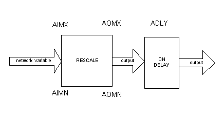
This is the default mode of operation, the humidifier output can be driven from any portion of the Heat Demand or Cool Demand signals received from the AHU controller. These demands are processed by the Rescalable driver code and the settingsare AIMX etc for the Heat Demand portion BIMX etc. for the Cooling portion.

An example will help to explain the settings
If the humidifier (Evaporative Cooler) is being used in conjunction with a Dessicant Wheel controller then one may want to arrange for the Evaporative Cooler to stage up between say 40% cooling demand and 75% cooling demand, and not to operate at all during the heating cycle.
This would be achieved by setting AOMN, AOMX to zero to ensure no output from the heating rescaler and by setting BIMN 40, BIMX 75 which defines the input range the recale is to work over and leaving BOMN 0 and BOMX 100 to provide 0 to 100% to the output driver stages. The on delay BDLY can be set to delay operation of the Humidifier if this is required.
The control becomes active when the associated AHU controller indicates that the building is Occupied or in warm-up and the AHU supply and extract fans are running.
The resultant demand output is passed to Channel 1 (normally heating) of the universal driver which can be set to provide the correct style of output, analogue output, sequence output, or raise lower output according to the type of hardware.
Closed Loop Control CMDE=1
The Humidity controller controls the connected humidifier to maintain the Return Air Humidity at Humidity setpoint. The measurement of Return Air Humidity is provided by an intelligent TRH sensor type RHR which must be registered to the AHU controller. The Humidity setpoint has a deadband associated with it and the controller also provides a network variable output which could be used to control de-humidification.
The control becomes active when the associated AHU controller indicates that the building is Occupied or in warm-up and the AHU supply and extract fans are running.
The resultant demand output is passed to Channel 1 (normally heating) of the universal driver which can be set to provide the correct style of output, analogue output, sequence output, or raise lower output according to the type of hardware
The second, channel 2, driver output can be used to control the reservoir solenoid valves. The output will change to 5V (50%) when the supply water solenoid is required and then change to 10V (100%) when the controller has been running the humidifier for a continuous period of 2 hours (configurable using RDLY 0- 10hours). It is intended that a Sontay RM2 relay module is connected to the output and the supply solenoid is switched using the normally open contacts of the first stage relay, and the drain solenoid is switched using the normally closed contacts of the second stage. The second stage can be thought of as 're-circulation mode'. When this stage is on the drain solenoid will be off thus re-circulating the return water.
This controller uses the universal driver code, found in other SeaChange products. The analogue outputs can be set to provide 0-10V or stepped outputs to drive active relay modules e.g. Sontay RM range.
The first 'H' channel of the driver is the demand signal for the humidifier, the second 'C' channel is used to drive the water reservoir solenoids.
The default settings for the AOP board provide two 0-10V analogue outputs while for the 3R board the driver is configured as a 3 step sequence to drive a staged cooler.
There are two plots setup as normal on the first two
'sensors'.
Plot 1 Measured RH
Plot 2 Control output
This controller uses Configurable
Plots like most of the other SeaChange controllers.
The plots are now automatically re-scaled within the
controller to achieve the best resolution for the data recorded. This happens at the end
of every 96 readings when new maximum and minimum settings are calculated and also if a
new value is outside the current range settings.
Since this is a new issue refer to
Config Tables