
|
Feature Notes
|
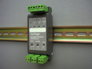
Secondary Circuit Controller
|
|
Features new this issue are in RED text |
VTC / DIN / 3T / ...
|
VTC / DIN / AOP / ...
|
Main FeaturesControls a Secondary LPHW or Chilled Water Circuit - Pump and Valve ControlVariable Temperature (VT) or Constant Temperature (CT) ControlWeather Compensation option for Heating CircuitsCollates Demand Signals from Multiple ZonesDemand routing: allows for transmission and reception of demand signals to and from other sub systems connected by ethernet.HT version has routine to handle control of steam valves |
 |
  |
Input 3-4 |
Optional Sensor |
Input 5-6 |
Flow Sensor |
INMD = 0 |
|
SACT = 0 |
Control on control sensor only |
SACT = 1 |
Control on average of two sensors |
SACT = 2 |
Control on maximum of two sensors |
SACT = 3 |
Control on minimum of two sensors |
Input 3-4 |
External occupancy VFC input |
Input 5-6 |
Flow Sensor |
SACT = 0 |
|
INMD = 1 |
Occupancy determined by own |
INMD = 2 |
Occupancy determined by own |
INMD = 3 |
External occupancy signal only |
Input 3-4 |
External monitor / alarm VFC input |
Input 5-6 |
Flow Sensor |
SACT = 0 |
|
INMD = 4 |
Monitor Input if ALRM = 0 Alarm Input if ALRM > 0 |
INMD = 5 |
Pump readback monitor |
ALST = 0 |
0 = Alarm State, 1 = Normal |
ALST = 1 |
0 = Normal, 1 = Alarm State |
NOAL |
No Alarms. |
SENF |
Sensor Failed. |
EXTN |
External alarm generated by VFC input. |
CNDF |
Condensation Failure |
PMPF |
Pump Fail (readback alarm) generated by VFC input (INMD = 5) or registered PCO Submodule. |
STOP |
System STOP alarm received. |
Heating |
Cooling |
Output A |
Output B |
Output C |
/ 101 |
/ 201 |
Time Proportional |
Not used |
Occupation or Optimum start switch |
/ 105 |
/ 205 |
Valve Open |
Valve Close |
Occupation or Optimum start switch |
/ 108 |
/ 208 |
Sequence 2 triacs at 33% and |
66% of demand |
Occupation or Optimum start switch |
/ 109 |
/ 209 |
Sequence 3 triacs at 25%, |
50% and |
75% of demand |
Heating |
Cooling |
Output A |
Output B |
Output C |
/ 721 |
/ 821 |
0-100% demand = 0-10Vdc |
Occupation Switch or optimum start switch |
Not available |
Input Configuration (3T and AOP versions) |
|
Input 3-4 ‘input a’ |
Return Sensor (optional) or VFC status / alarm / occupancy |
Input 5-6 ‘input b’ |
Flow Sensor |
ENER-G Controls
ENER-G House
Daniel Adamson Road
Salford
Manchester
M5 2DT
phone 0161 7457450
fax 0161 7457457
www.energ.com
www.seachange.co.uk
www.smartkontrols.co.uk