Feature
Notes

Configuration Tables

Data Sheet

Wiring and Applications

History

Feature Notes

Datasheet


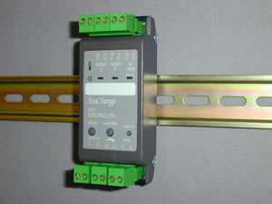
VAV Controller
with 2 x 0-10V DC Outputs

Latest released version is 4c3

Document last updated 01/11/2001
Recent features not included on Data sheet are in
RED text

VAV / DIN / AOP /...

Main Features

Controls VAV Terminal Units

Works in conjunction with Belimo “Compact” Volume controller

Controls a reheat battery (if fitted)

Local User Interface or Actual Volume monitoring options

Summary Features

General

The VAV Controller controls a Variable Air Volume Terminal Unit (VAV Box); it works in conjunction with a Belimo “Compact” Volume Controller. The Belimo controller has a built-in volume sensor which senses the volume of air flowing through the box. As the pressure in the ductwork system feeding the box fluctuates, the Belimo controller maintains a constant volume through the box; this is called Pressure Independent control.
The SeaChange VAV Controller controls the space temperature; it sends a Desired Volume signal to the Belimo Controller via a 0-10V DC output. As the VAV Controller’s cooling demand increases, it will send a demand for increasing volume to the Belimo Controller. This technique, where the output from the (SeaChange) Temperature control loop is used as the setpoint for a second (Belimo) volume control loop is called Cascade Control.

Operation

A SeaChange Zone Controller must be used to set the operating times for its group of fan coils and to provide an override push button to extend operation outside normal hours using Occupancy Supervision Interconnects. Alternatively, the Zone Controller can be used to set both operating times and setpoints for the controllers using Setpoint Supervision Interconnects. One Zone Controller has the flexibility to control from 1 to 199 VAV boxes at any one time on a single network.
This makes the SeaChange system equally suited to controlling numerous VAV boxes in a single open plan office zone as it is to providing effective one to one unit zone control for cellular office or hotel bedroom applications.
Because it is modular and incorporates plug and play engineering, a SeaChange VAV control system can be easily and inexpensively adapted to cope with additional zones or VAV boxes changed to work in different zones as offices “churn” over time.

Temperature Control

Temperature control is based on the VAV box’s return air temperature (if appropriate) or, more usually a wall-mounted temperature sensor. The sensor is wired to the Controller’s input terminals.

Local User Interface

The /001 variant allows the second input to be used for a local user interface. If costs do not allow each VAV box to be provided with a Zone Controller for individual user interface, a combined Temperature sensor, setpoint adjuster and occupancy switch can be applied so that the temperature can be adjusted and the unit turned On/Off locally. Other fan coil controllers can then be controlled as slaves.

Actual Volume feedback

The /002 variant allows the second input to be wired to the 0-10V DC Actual Volume output from the Belimo Controller. This allows the Actual Volume to be monitored (using Doorway Supervisor, or a Zone Controller using User Displays) which can be useful when commissioning; if the Actual Volume is consistently lower than the Desired Volume, this indicates that the box is starved of air, probably indicating that the Supply Air pressure setpoint needs to be increased (see Static Pressure Controller Data Sheet). A future SeaChange development will allow dynamic control of the VAV AHU’s volume based on box volume shortfall; contact SeaChange for further details.

Description of Features

Temperature Control

Room / Return Air Control from local sensor

A Return Air (or Room) Temperature sensor must be fitted. The VAV Controller will control Return Air temperature to a fixed setpoint set using Configuration parameter SPFC, or an adjustable setpoint, using a Zone Controller (see Registration, later). A deadband may be set (using the SPDB parameter) which will prevent cycling between heating and cooling and reduce energy usage. This will work with SPTY set to 0 or 1.

Room Control using a Zone Controller

With no Sensor fitted, the VAV Controller enters “Slave” mode, and will adjust its Desired Volume output for cooling (and reheat valve position, if fitted). on the basis of the Control Demand signals received from the Zone Controller (or “Master” VAV Controller -see later), i.e. if the Zone Controller is demanding 50% Cooling, the Desired Volume will be driven to 50% of its full scale value. (This is called Open-Loop Control ). This will work with SPTY set to 0 or 1
If a sensor is fitted, but it is desired not to use the sensor for control, the VAV Controller can be forced into “Slave” mode by setting SPTY to 2; this selects the Control Demand Interconnect connection from the Master to be active, and the Controller will behave as above. The sensor can be used for monitoring.
Example : Temperature controlled by Zone Controller
Zone Controller will bring the VAV Controller during Occupancy, Optimum Start, Fabric Protection and Occupancy Override. Zone Controller’s sensor and control loop are used to control the temperature. VAV Controller operates to Control Demand signal received from Zone Controller. VAV Controller operates in this mode if no sensor is fitted whatever the setting of SPTY parameter. Setting SPTY to 2 will force this mode even if a sensor is connected.

Interconnects

Occupancy Supervision and Local Override

Occupation status for one, or many VAV Controllers (up to 199) are set at a Zone Controller. The Zone Controller holds the Occupation Times, and the Occupancy Status is transferred to the VAV Controllers using Occupancy Supervision ( VAV Controllers do not have their own Occupation Times, you must supervise them from a Zone Controller ).
The Zone Controller takes care of Optimum Start and Fabric Protection for the zone of VAV boxes that it is controlling, so it is important that the Zone Controller’s temperature sensor is mounted in a representative part of the space. The VAV boxes will be brought into Occupancy by the Zone Controller during Optimum Start, normal Occupancy period, or because the temperature has dropped and the Zone Controller is in Fabric Protection mode. Also, the Occupancy Times may be overridden by the Override pushbutton on the Zone Controller in the usual way, giving configurable timed extension to occupancy (see Zone Controller Data Sheet).
Additionally, a local switch may be used in order to put the Fan Coil Controller into an Occupied State; this can either be used exclusively to control occupancy (e.g. a Meeting Room) or it can be used in conjunction with a Zone Controller to provide an extension to occupancy. In either case, the Controller requires a maintained contact closure (latching switch) in order to give an Occupied State; if a timed extension is desired, an external timed latching contact must be used. The parameter INMD is used to determine whether the external signal is to be used exclusively, or as an OR function with a Zone Controller’s Occupation Times.
Example : Occupancy Supervision
Zone Controller will bring the VAV Controller into Occupation during Occupancy, Optimum Start, Fabric Protection and Occupancy Override. VAV Controller operates to its own setpoint.

Setpoint Supervision and Local Setpoint Adjustment

The VAV Controller may operate to a local setpoint, set on parameter SPFC, or alternatively a Zone Controller may be used to determine the Setpoint for one or many Fan Coil Controllers. This is called Setpoint Supervision.
Example : Setpoint Supervision
Zone Controller will bring the VAV Controller into Occupation during Occupancy, Optimum Start, Fabric Protection and Occupancy Override. VAV Controller operates to Zone Controller’s setpoint.
The setting of the SPTY parameter determines which value is used for the setpoint; setting SPTY to zero will mean that the Zone Controller will be used for Occupancy Supervision, and its setpoint will be ignored by the VAV Controller (it will use its own local setpoint). Setting SPTY to 1 will enable Setpoint Supervision; adjusting the Zone Controller’s setpoint will cause it to be sent to the VAV Controller.
A VAV Controller may have a Local Setpoint Adjuster which is a simple wall-mounted potentiometer wired directly into the VAV Controller’s input terminals; adjusting this will adjust the offset value (limited to +/-5 Deg.C). The offset value and a value set on the internal parameter SPTR are added (or subtracted if the value is negative) to the setpoint set on SPFC to produce the operating setpoint for the controller. Note that using a simple potentiometer means that some of the energy saving benefits given by the Zone Controller (e.g. resetting the setpoint to a default value at the start of each occupancy period) are not possible.

Master - Slave VAV Controllers

A VAV Controller can also be used to provide Setpoint Supervision for a group of "Slave" VAV Controllers; this would be used when an Open-Plan area is fed by several VAV boxes, and only one Local Setpoint Adjuster is required. The Local Setpoint Adjuster is wired to one of the VAV Controllers, which then becomes the "Master" of the group.
It will send its setpoint set on SPFC plus the offset applied by the Setpoint Adjuster plus any value set on SPTR to all of the “Slave” Fan Coils registered to it (see Master/Slave diagram in datasheet) which will then use the resultant value as their own SPFC value. Individual trims to this setpoint can be set up in each “Slave” using its SPTR parameter, if desired.
Example : Master - Slave VAV Controllers
Master VAV Controller operates to Zone Controller’s setpoint but this can be modified by Local Setpoint Adjuster. Slave VAV Controller operates to Master VAV Controller’s current setpoint.

Maximum & Minimum Volume

VAV boxes usually have maximum and minimum design volumes assigned to them by the mechanical designer; the minimum volume ensures a minimum quantity of fresh air enters the space, whilst the maximum volume ensures that the zone does not receive too much air and upset overall system balance. These parameters may be set either using the settings in the Belimo Controller, or by setting the MAXV and MINV parameters in the VAV Controller. The advantage of the latter method is that the volumes can be adjusted remotely during commissioning or later if the building is altered, and also that this allows for some of the boxes in a system to be turned off if that zone of the building is not occupied.
Normally, when the VAV Controller is out of occupancy, the box will close fully (unless minimum volume settings have been made in the Belimo Controller). This allows the main plant to continue running to serve other zones. If however for mechanical reasons it is necessary for the boxes to remain partly open during non-occupancy, an absolute minimum volume may be set using the MNVA parameter; this value applies at all times.

ReHeat Battery control

If a reheat battery is fitted, this may be driven from channel ‘A’ output, which provides a 0-10V DC signal to drive a valve actuator. Alternatively, if an electric battery is fitted, Engineering Parameters HYTP and HSTG may be set to allow the use of a Solid-State Relay (SSR). Contact SeaChange for the parameter settings and advice on the type of SSR that you need.
Sometimes, reheat batteries need a minimum air flow over them in order to give full duty which exceeds the minimum fresh air volume set on MINV. This can be accommodated by setting parameter REHT to the % volume needed by the reheater at full output. As heating demand increases, the reheat output will increase from 0 to 10V, while the Desired Volume output will increase from MINV to REHT.

Heating / Cooling VAV systems

The VAV Controller may be used in applications where the VAV boxes are being fed with hot or cold air from a central plant, depending on the current demand from the space. The Central Plant may be controlled by a Heat Pump Controller or Floor Controller (see relevant Data Sheets for full details). In brief, the Heat Pump or Floor Controller will collate the demand signals from all of the registered VAV Controllers, and decide on the temperature of the air that they need.
The Heat Pump or Floor Controller measures the Supply Air temperature and broadcasts it on the network; the VAV Controllers receive the information, and will decide whether to open the VAV Box or not. They do this by comparing their current setpoint with the temperature of the Supply Air. If the Supply Air temperature is below the box’s current setpoint (less half of the deadband), and the box requires cooling, the box will open; if the Supply Air is at a higher temperature than this and the box requires cooling, the box will remain closed to its minimum volume (as the air would have no effect, or a heating, rather than a cooling effect).
In order to make the VAV Controller check the Supply Air temperature before opening, it is necessary to set the REHT parameter (normally used for setting Reheat volume - see ReHeat section) to -1.
Also, it is necessary to divert both heating and cooling control outputs to the same physical output channel; this is done by adjusting Engineering Parameters HYTP and HSTG; contact SeaChange for advice on setting these parameters. Because of this driver signal re-direction, the Desired Volume output is now taken from Channel ‘A’ (usually the terminals for the ReHeat connection). It is not possible to drive a ReHeat battery when using this mode of operation.

Occupation Only

The selection of OCC or OSS is now made by setting OCCO to 1 on controllers where the control is only required when the building is in occupation. The default is for control during OSS and OCC.

Frost Protection

This is defined with a config parameter FRPT and it defines the controllers action when it receives a 'frost alarm' from the boiler controller.
FRPT = 0
No action (default)
FRPT = 1
Heating output to 50%
FRPT = 2
Heating output to 50% and pump/fan enabled

Window Contact, General Alarm or Monitoring

A Volt-free window contact may be wired into the Controller’s input terminals and used to disable the VAV box if the Window is opened, preventing energy wastage. This function could also be applied to other inputs which would require the Fan Coil to shut down. Alarms to the supervisor can be enabled or disabled using the ALRM parameter; the ALST parameter is used to set the contact sense. I.e. whether an opening or closing contact will generate an alarm.
The Input may be alternatively used for general monitoring, either with or without alarm generation.
The correct mode of operation is determined by the INMD parameter.
A switched volt free contact can be connected to input terminals 3-4 (/001 variant only) which when made will force the FCU to Occupied. This is achieved by adding an extra config variable input mode INMD. The following values are supported:
INMD = 0
Normal operation, input not used on /001 variant (/002 variant uses input for 0-10Vdc Actual Volume)
INMD = 1
Occupied is External AND normal occupation (window contact) (/001 variant only)
INMD = 2
Occupied is External OR normal occupation (outside normal hours) (/001 variant only)
INMD = 3
Occupation controlled by External signal only (/001 variant only)
INMD = 4
Input used as an external alarm, alarm state defined by ALST (/001 variant only)
If the switch is wired in series with a 1K resistor and a 10K potentiometer Occupied/ Non occupied plus a 5 degree trim (operational only whilst occupied) is possible. The trim is slightly non linear (the applied resistance is affected by the parallel resistance on the board which helps linearise the thermistor when fitted, mechanical centre position of the pot gives -0.7C) The zero point can be adjusted to give the correct (0 trim) by backing off any error using the software trim SPTR. Suggest pot is marked Hotter/Colder or +/- !
A resistance between 0 and 20K ohm will be considered to be Occupied, non Occupied is guaranteed for resistance values above 100K. The voltage generated by the pot will be converted to a setpoint Trim only for control modes SPTY 0 or 1.

Alarm Handling

The VAV Controller may be set to ignore alarm conditions, report them to a SeaChange Doorway Supervisor (either locally connected to the system, or via an autodialling modem), or to both report alarms and take some control action. The ALRM parameter is used to select the desired Alarm Mode, whilst ALST is used to set the sense (i.e.. whether a closing or opening contact generates an alarm).
The VAV Controller generates an alarm if the sensor fails and also if the external alarm input is used.
The VAV Controller may be set to respond to the STOP System Stop Alarm which is generated by a Boiler Controller; this can be used to shut down the entire control system, or parts of it, if a particularly critical event occurs.
NOAL
No Alarms.
All alarm conditions cleared in this Module.
SENF
Sensor Failed (only sent if SPTY = 0 or 1)
EXTN
External alarm generated by VFC input (/001 version only)
STOP
System STOP alarm received.
All outputs shut down.

Registration and Commissioning

Pre Commissioning Checks

Power Up

On initial power up of the module there will be delay of between 10 to 60 seconds before the temperature LED lights. This delay has been incorporated so that when many VAV boxes are controlled on the same circuit their power requirements will be spread over this period.

Registration

Registration is the simple process by which logical connections are made between Controllers in a SeaChange system; it is done during commissioning and involves pressing buttons on the Controllers in a specific sequence.
For further details of the registration process, see our ‘Design and Commissioning Guide’ publication.

Address Allocation and System Housekeeping

Like all SeaChange Controllers, the VAV Controllers must be registered with other modules in order to create a working system. During the Registration procedure, the address of each Controller is allocated by the module that contains System Housekeeping. Check that you have an appropriate System Housekeeping Module; see our ‘Design and Commissioning Guide’ publication.

Interconnects

The VAV Controller must receive signals from a Zone Controller, either Occupancy Supervision or Setpoint Supervision, or Control Demand signals (see Temperature Control section). It may also send signals to other modules (e.g. a Heating Demand signal to the Module which provides hot water for its ReHeat Battery).
These Interconnects are put in place by Registration; again, see our ‘Design and Commissioning Guide’ publication.

>Manual Override

Allows the outputs to be exercised during comm-issioning and maintenance activities. Holding the Manual Override button pressed until the Status Lamp flashes green will cause the controller to be switched from automatic to manual control and the Box will control to normal setpoint. This is called Occupancy Override mode. Subsequent pressings of the manual override button will cause Manual Hand mode to be selected:
  1. Hold down Override until Status lamp flashes
    Controller changes to Override Mode and becomes Occupied, controlling to current Occupied Setpoint.
  2. Press Override again
    Controller changes to Manual Mode and output is set to 100% heating, temperature lamp shows red.
  3. Press Override again
    Controller changes to Manual Mode and output is set to 100% cooling, temperature lamp shows amber.
  4. Press Override again
    Controller cancels Manual Override and reverts to automatic control.
As this feature does not time out, care should be exercised to ensure the module is returned to the automatic mode on completion of the commissioning or maintenance activities.
Manual Override can also be achieved via Doorway;
1) AUTO and OVRD can be used together to put the Controller into Occupancy Override mode using the syntax:
[Zn]W1(S)/auto/override/10/12/W2(S)
When clicked, this brings up the ON/OFF/AUTO dialog box which allows the user to select Override ON, Override OFF or Automatic control.
The screen display will show override (in red) or auto (in green).
2) HAND and MANL can be used together to put the controller into Manual Hand mode using the syntax:
[Zn]W5(S)/hand/auto/12/10/C83(V)
Clicking on the point will bring up a dialog box which allows hand or auto to be selected with radio buttons and the output level to be set in a text box or using the slider controls. The output can be set between -100, full cooling through to +100 full heating. The screen display will show hand (in red) or auto (in green).

Options and Product Codes

VAV Controller

VAV / DIN / AOP / [ option]

Options

Option

Output A

Output B

Input 3-4

/ 001
Reheat Battery 0-10v DC (optional)
Desired Volume 0-10v DC
Setpoint / VFC status / alarm / occupancy
/ 002
Reheat Battery 0-10v DC (optional)
Desired Volume 0-10v DC
0 - 10V DC input for actual volume signal from Belimo controller


Input Configuration

Input 3-4
See options table
Input 5-6‘temp’
Temp Sensor (optional)
smartkontrols Ltd
8 Horsted Square
Bell Lane Business Park
Uckfield East Sussex
TN22 1QG
phone 01825 769812
fax 01825 769813
e-mail sales@smartkontrols.co.uk
http:// www.smartkontrols.co.uk